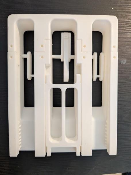

Team ORCA hydraulic can punch assembly
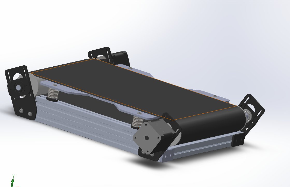
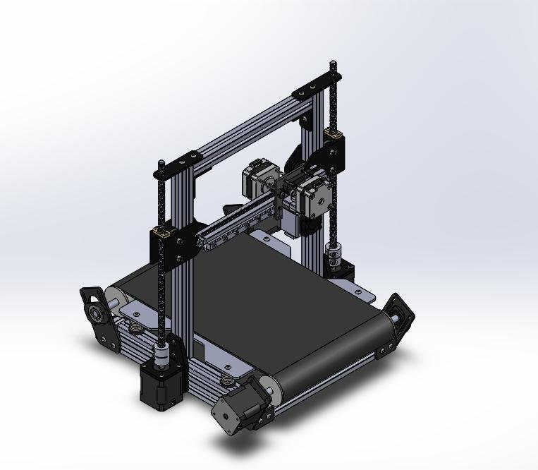
Conveyor 3D printer final assembly
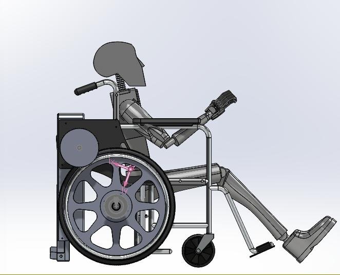
Wheelchair stair climber CAD model
Four-bar mechanism physical model
Custom speaker enclosure project
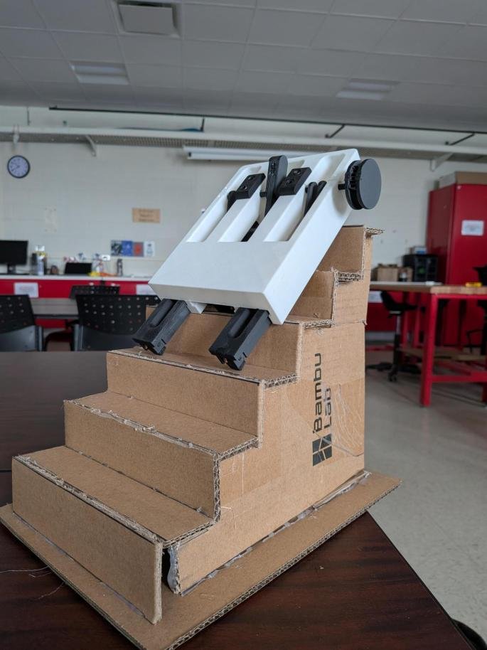
Stair climber scale model testing

Mechanical Engineering Portfolio

EWENBUILDS.xyz

Callum Ewen — Mechanical Engineering student at the University of New Brunswick. SolidWorks CSWA certified, FIRST Robotics team executive and lead designer, and Engineering Makerspace Facilitator.

Engineering Work

Projects

Expand any project to read the full report, or download the original files.

Hydraulic Can Punch — Team ORCA cover image

ME 2125 · Overhead Rapid Can Assembler · April 2026 · Team of 5

Hydraulic Can Punch — Team ORCA

A hydraulic press that punches cans to a target 5.5 cm height and automatically sorts them. A 185 kN cylinder at 25 MPa drives a guided punch and die, and a conveyor feeds a two-bar length filter that accepts good cans and rejects oversized or undersized ones.

HydraulicsMachine DesignSolidWorks

Abstract

This report presents the design of a hydraulic can punching mechanism developed to punch cans accurately and sort them based on the required final length. The system uses a hydraulic cylinder to deliver the punching force, a guided punch and die arrangement for stable and even force application, and a conveyor-based filtering section to separate cans by final height.

The design emphasizes feasibility, repeatability, ease of maintenance and safe assembly by using standard fasteners and removable components rather than heavily welded joints. Calculations were completed for cylinder sizing, stroke speed, flow rate, hydraulic power and force verification.

Introduction & Objectives

Can manufacturing involves blanking, drawing, wall ironing, trimming, necking and finishing. This project focuses on the punching and sorting stage: a hydraulic press-based mechanism must punch cans and produce a product that meets dimensional constraints, while also checking whether each punched can meets the required final size.

  • Punch cans accurately and consistently to the required final dimensions with smooth, controlled operation.
  • Use a guided punch and die so force is evenly distributed, reducing defects such as wrinkling.
  • Include a simple length filter that automatically separates acceptable cans from oversized or undersized ones.
  • Be easy to assemble, repair and modify using standard bolts, shafts, bearings and removable parts.

Design Concept

The assembly consists of a hydraulic cylinder mounted at the top of the frame, a guide mechanism, a fixed die, angled spring holders, a discharge path onto a conveyor, and a two-bar length filtering system.

  • Hydraulic cylinder / press — provides the vertical punching motion, designed for 185 kN of punch force at 25 MPa.
  • Guide section — keeps the punch aligned so force is distributed evenly, improving consistency and preventing wrinkles.
  • Die — mounted in a slot below the guide as the receiving and cutting support; machined from metal block or plate.
  • Punch geometry — sized around a 6.6 cm can diameter, with an accepted final height of 5.5 cm.
  • Angled spring holders — guide the can on the downstroke and help it slide off as the punch retracts, reducing jams.
  • Conveyor — carries punched cans to the sorting section without manual handling.
  • Length filter — a bar at 5.6 cm removes cans that are too tall; a second bar stops and accepts 5.5 cm cans; shorter cans continue on and are discarded.

Manufacturing Considerations

  • Legs: 2×2 in steel square tubing, drilled on a mill/CNC for the L brackets, M7 threads with Loctite to resist vibration.
  • L brackets (frame and conveyor): plasma-cut sheet metal bent on a press brake.
  • Top, mid and base plates: CNC milled from higher-carbon steel for precise hole placement — especially the central hole the can is formed through.
  • Sorting plate: high-precision 3D printing (~0.08 mm tolerance is acceptable).
  • Custom hydraulic cylinder, standoffs and cylindrical parts: CNC lathe. Parts tested by a third party for tolerance.

Calculations

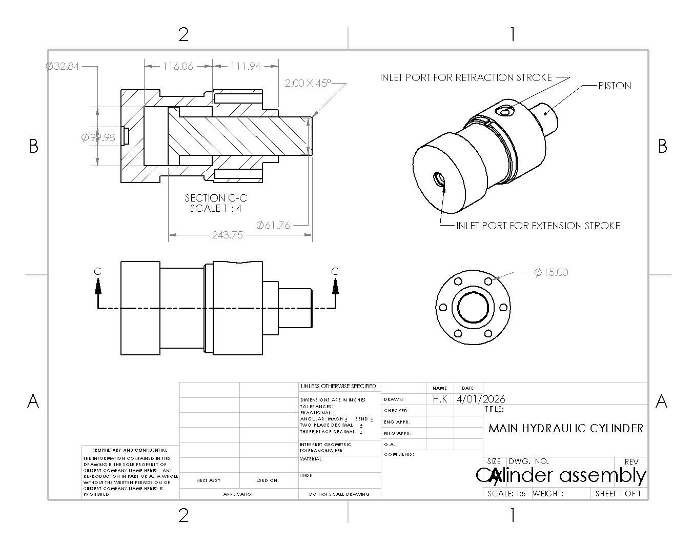
Given: system pressure P = 25 MPa, required punch force F = 185 kN, stroke length L = 120 mm, total cycle time 0.50 s (0.25 s extend, 0.25 s retract). Governing relations: A = F/P, D = √(4A/π), v = L/t, Q = A·v, Power = P·Q.

ParameterValueUnits
Equivalent bore diameter97.1mm
Extension / downstroke area74.00cm²
Retract-side effective area43.01cm²
Piston speed (each stroke)0.48m/s
Extension flow rate213.12L/min
Retraction flow rate123.87L/min
Extension hydraulic power88.80kW
Retraction hydraulic power51.61kW
Available extension force185.00kN
Available retraction force107.53kN
Figure 3: Hydraulic Cylinder Assembly Drawing

Bill of Materials

PartQtySupplierApprox. Price
Hydraulic Cylinder1Manufactured$500
Hydraulic Pump (PLSD 21, ~10,000 psi electric)2Enerpac$7,000 each
Hydraulic Gear Pump (6296K44)1McMaster-Carr$800
Class 8.8 Steel Hex Head Screw1 pack of 25McMaster-Carr$15
Class 8.8 Steel Hex Head Screw2 packs of 10McMaster-Carr$10 per pack
18-8 SS Top-Lock Locknut1 pack of 5McMaster-Carr$12 per pack
18-8 SS General Purpose Washer1 pack of 100McMaster-Carr$20
Linear Motion Shaft2McMaster-Carr$40 each
ServoCity 1/8" ID Flanged Ball Bearing2Amazon / Robot Shop$15 each
DC Gearbox "TT" Motor, 200 RPM1Adafruit$8
Carbon Spring Steel Compression Springs5Amazon$10 total
Estimated Total$15,500–$16,000

Feasibility & Viability

The cylinder delivers the required punch force, and the guide and die give stable, repeatable motion. Standard bolts, shafts and bearings make maintenance easy — a worn guide, bracket or spring holder can be replaced without rebuilding the structure. The conveyor and filter add a built-in quality-control step.

A limitation is the high flow rate (~213 L/min) and power (~88.8 kW ideal) needed for a 0.50 s cycle, so pump and motor selection must be careful. Slightly reducing operating speed or optimizing the stroke would lower that demand.
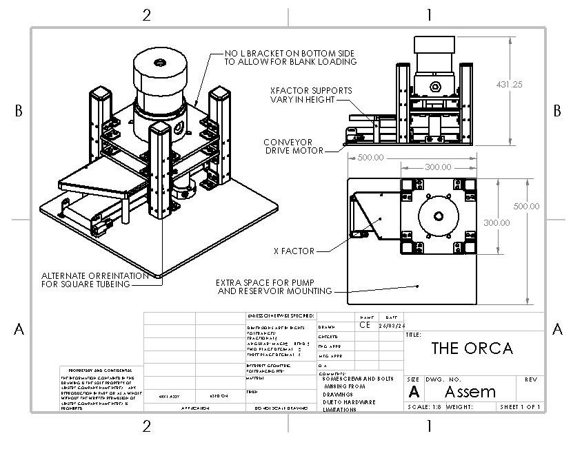
Figure 2: ORCA Assembly Drawing

Conclusion

The final design is a hydraulic can punching and length filtering mechanism that punches cans and automatically separates them by final height. Calculations show the cylinder can generate the required force and the hydraulic system can deliver the necessary motion, flow and power. It is feasible because it meets the force and dimensional requirements, and viable because it uses practical components, bolted assembly and a built-in filtering stage.
Four-Bar Linkage Mechanism cover image

ME 2145 · Group 9 · February 2026 · Team of 4

Four-Bar Linkage Mechanism

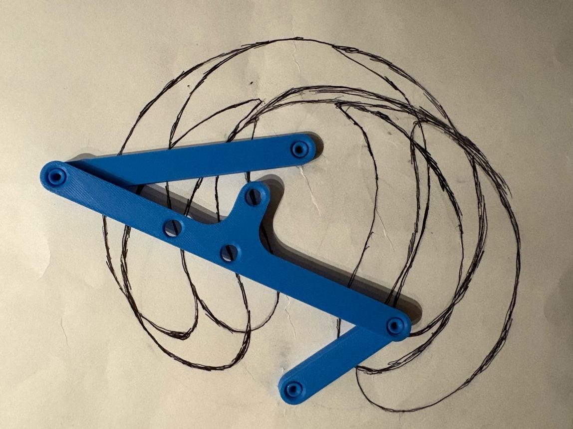
A fully 3D-printed Grashof change-point crank-rocker-rocker designed in SolidWorks and simulated in MATLAB. Coupler curves were traced physically and in simulation, revealing how coupler offset and input dynamics change the curves near the change point.

KinematicsMATLABSolidWorks3D Printing

Abstract

This report covers four-bar link design, how four-bar links are classified, the relationship between coupler curves and coupler position, and change points, supported by mathematical calculations describing the mechanism.

Classification & Design

The mechanism is a Grashof change-point crank-rocker-rocker: the sum of the longest and shortest links equals the sum of the other two, and the shortest link (link 2) is driven. Ground link = 10 cm, input crank = 5 cm, coupler = 15 cm, output rocker = 10 cm — so 15 + 5 = 10 + 10 = 20 cm.

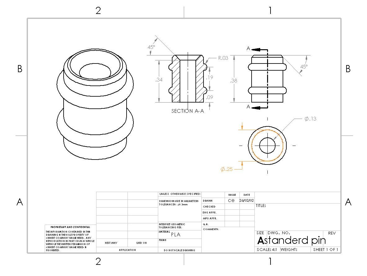
The assembly was designed in SolidWorks and fully 3D printed. Custom 3D-printed push pins were press-fit into each joint for full rotation. Coupler points were placed along the coupler, with extra material at mid-section so a point could be offset in Y. Paper served as the ground link.

Figure 4: Push Pin CAD Drawing

Coupler Curves

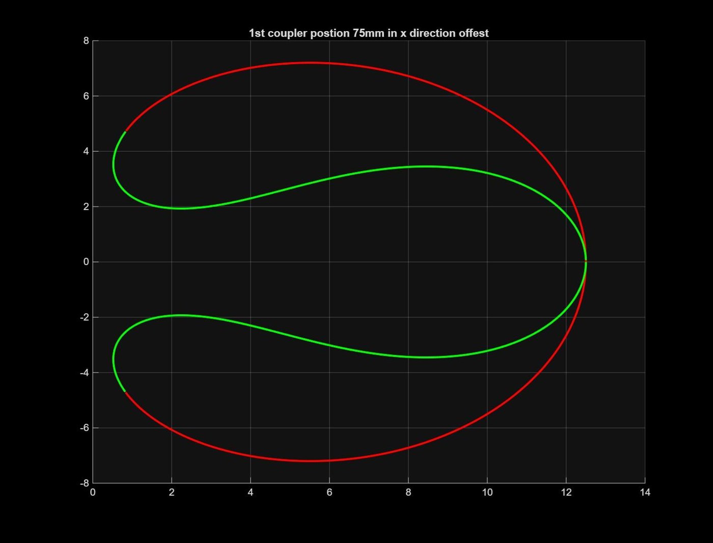
  • Curve 1 — 75 mm in X from link 2. Classified as a double teardrop (a mirrored teardrop) because of the change point. Without Y offset, the curves meet at exactly one point.
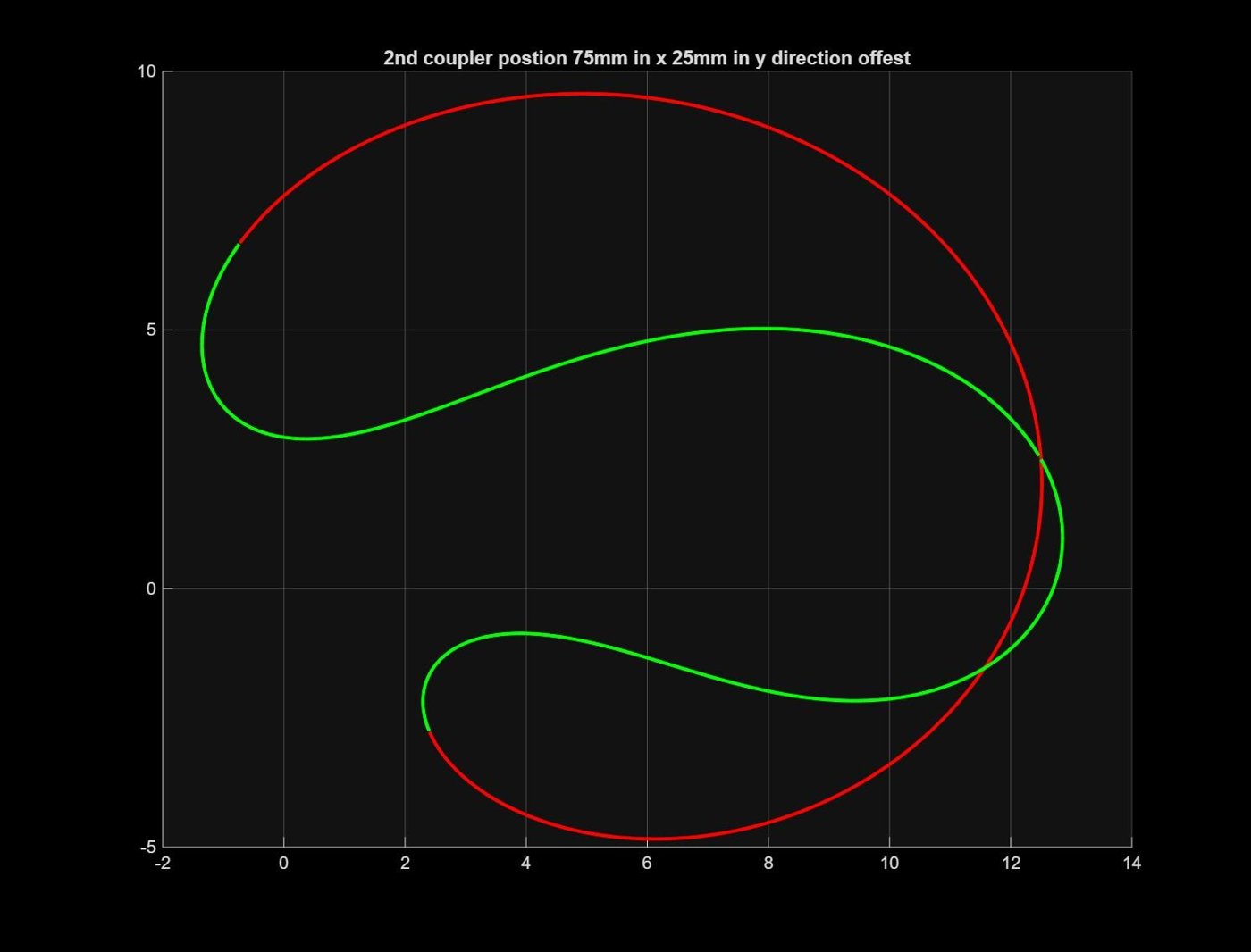
  • Curve 2 — 75 mm in X and 25 mm in Y. An asymmetrical crunode or triple loop; the centre lines briefly overlap, likely due to the Y offset.
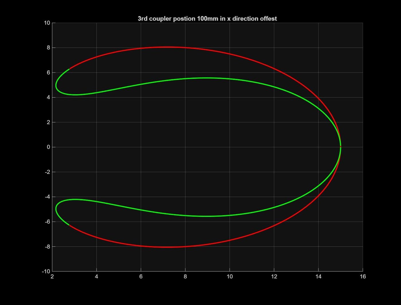
  • Curve 3 — also a double teardrop, but narrower than curve 1, suggesting a relationship between distance from link 2 and curve thickness.
  • In every case, the MATLAB simulation matched the physically traced curves.
Figure 1: Coupler Curve #1
Figure 2: Coupler Curve #2
Figure 3: Coupler Curve #3

MATLAB Code

The code sets link 2 to 50 mm for a full 360° rotation and uses the law of cosines to solve the geometry. Coupler points are traced from their X, Y positions as multi-coloured curves. Findings: the further the coupler point in X from link 2, the thinner the curve; offsetting in Y creates an overlap at the change point.

Limits of Movement

Link 2 (input crank) completes a full 360° rotation. Link 4 (output rocker) oscillates between two toggle positions, sweeping 4π/3 rad (240°). These limits define the operating range and the transition points of the coupler curves.

Transmission Angles & Toggle Points

Two toggle positions exist, mirrored about the x-axis, showing the mechanism is symmetrical about the ground link. Maximum and minimum transmission angles occur when the crank is collinear with the ground link — the triangle base becomes (L1 + L2) or (L1 − L2). The minimum-angle position is also a toggle position.

Applications

  • Automatic closers for heavy steel doors, paired with an electric motor.
  • Pushrod (OHV) engines — the cam lobes act as the crank driving the pushrod and rocker arm, with the engine block as the frame.
  • Oil pumpjacks — the crank drives the pitman arm and walking beam, with the ground as the frame.

Change Point Results

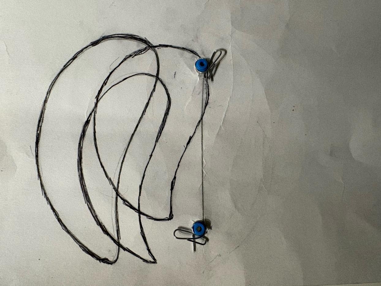
Depending on where force was applied, how fast the input moved and how much force was used, the linkage took different paths. A SolidWorks animation (no mass or gravity) produced only a half coupler curve, while a full simulation produced the double curves seen in MATLAB.

At low angular velocity the mechanism lacks the inertia to pass the change point and traces a half curve; with more speed, momentum or leverage through the coupler, it pushes through and traces the double curve. Geometry defines the motion constraints, but operating conditions shape the real behaviour near change points.

Figure 9: Physical model stopped at change point

Conclusion

The mechanism was confirmed as a Grashof change-point crank-rocker-rocker, designed in SolidWorks, simulated in MATLAB and physically tested. Two mirrored toggle points define the curve limits. A Y offset produces overlapping curves near the change point, and X offset is inversely proportional to curve thickness. Physical testing produced six different coupler curves and showed how inertia and applied force decide between half and double curves.

My Contributions

MATLAB code, 3D print / SolidWorks design, abstract, classifications and design, formatting, editing, and list of figures.

Wheelchair Stair Climber cover image

ME 2145 · Wheelchair Stair Assistant · March 2026 · Team of 4

Wheelchair Stair Climber

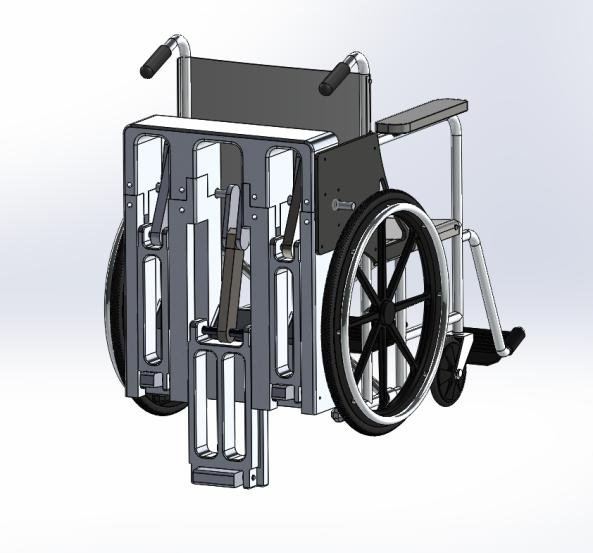
A user-powered crank-slider attachment for standard folding wheelchairs that climbs stairs using arm motion. Designed for an 8" stair rise with a 9" stroke and 2:1 drive, then validated with CAD centre-of-gravity studies, stress analysis and a ¼-scale 3D-printed model on scale stairs.

Mechanism DesignStress AnalysisSolidWorksPrototyping

Introduction

Stairs remain an obstacle for most wheelchair users. The goal was a stair-climbing attachment compatible with most folding wheelchairs, ideally priced under $3,200 (the cheapest user-independent stair-climbing wheelchair available). It should be light yet solid (aluminum or titanium), safe (balance aids, guards, large factor of safety), durable for five years, and require no more than 100–150 lb of lifting force. Use is limited to dry indoor stairs.

Requirements

  • Attach to standard folding wheelchairs.
  • Be driven through arm movement and independently operated.
  • Be safe, and remove easily or stay compact so the chair can still fold.
  • Work for varying stair sizes without impeding normal wheelchair functions.
  • Climb or descend a flight of stairs.

Concepts

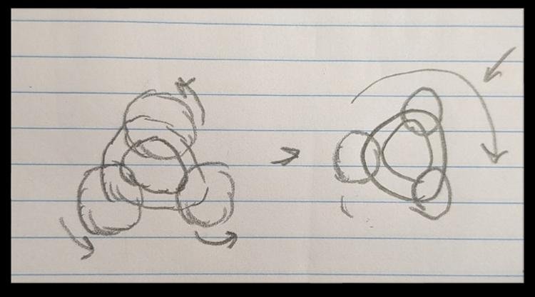
  • Concept 1 — a rotating three-wheel cluster like a stair-climbing cart. Rejected: too complex, hard to drive, and a high centre of gravity.
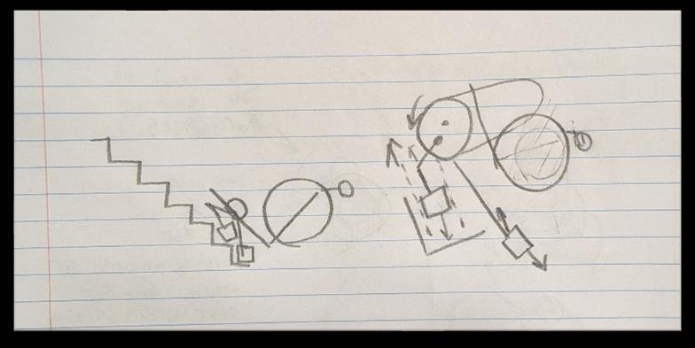
  • Concept 2 — two pistons driven by a rotating disk, mimicking feet walking upstairs. Clunky with a centre-of-gravity offset, but simplest to operate and least disruptive to everyday use.
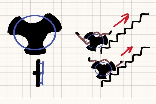
  • Concept 3 — a specially cut wheel profile that slots onto each step. Easy to make, but would need very large forces to climb and balance.
Concept 1 Drawing
Concept 1 Drawing
Concept 2 Drawing
Concept 2 Drawing
Concept 3 Drawing
Concept 3 Drawing

Final Design

Concept 2 was selected for its simplicity: two links, a slider and a crankshaft, powered by hand force geared up through a belt or chain.

  • Crankshaft — the crank and drive link.
  • Large link — upper and lower halves that wrap around the crankshaft.
  • Sliders — wide and narrow, 180° out of phase.
  • Feet — retractable pushing surfaces.
  • Base block — two-part housing for the mechanism, plus upper and lower mounts to the chair.
  • Wheels / pulleys — a wheel on the chair’s drive wheel drives a pulley twice its size to turn the crankshaft.

Design Synthesis & Forces

With an average stair height of 8", a 9" slider travel was chosen for an inch of safety margin. Offsetting the pivot 3" up and left to avoid interference gave a 4.24" drive link and a 9.09" push link.

Using a 200 lb user, 50 lb chair and 141 lb mechanism (aluminum 7075), the force parallel to the chair is 1229.8 N. With a 20" drive wheel and a 400 N (~100 lb) push, torque is 101.6 Nm; the maximum required output torque was 146 Nm, a 1.44:1 ratio — rounded to 2:1 for realistic pushing force.

Design Challenges & Changes

Early on, the sliders simply slid along the stairs instead of pushing. Ratcheting feet were added: they push in one direction and collapse on the return stroke, with a low-force 90° torsion spring returning them perpendicular to the slider.

A plate mounted to the wheel using the push-bar bolt pattern drives a gear shaft into the crank-slider. A spring-loaded pin (chosen over an over-centre mechanism for simplicity) lets the user disengage the climber. Tolerances were added after early 3D-printed parts didn’t fit.

Motion Analysis

At an assumed 10 rpm input (ω = 1.05 rad/s) and a 0.1077 m crank, the peak slider velocity is 0.113 m/s. Over the 0.2286 m stroke, one push takes about 2.02 s — practical, controllable and safe.

Verification

In CAD, every part was assigned a material and a human model was assigned “water” density; the centre of mass sat in the middle of the wheelchair. A ¼-scale 3D-printed model with fishing weights replicating the loaded centre of gravity was run by hand on ¼-scale 8" × 8" cardboard stairs and stayed stable at rest and while climbing.

Figure 10: Human Model Paired With Mechanism
Figure 9: 25% scale main block
Figure 13: Scale Model Testing

Force & Stress Analysis

  • Total force on the feet: 1229 N; maximum torque from an Excel sweep: 149 Nm.
  • Mechanism mounting bolts: 5.41 MPa — well under the M5 allowable.
  • Bolts to the wheelchair: 8.65 MPa — safe, though this could risk the hollow aluminum chair frame.
  • Crankshaft: 103 MPa maximum, a factor of safety of 4.5.

Manufacturing

The main blocks need the most attention due to internal pockets (filleted to avoid sharp corners). Blocks, links and sliders would be CNC milled; the crankshaft, pulleys and wheel drive CNC turned. Bearings are used only on the crankshaft, bushings elsewhere. At scale, casting could cut costs. The main wear concern is the ratchet teeth.

Bill of Materials

Custom parts were quoted through Xometry and hardware from McMaster-Carr and Studica. The mechanism alone came to $5,861.80 CAD, mostly from the top and bottom blocks; with the drive mechanism the total is about $6,361.72 plus ~$200 in hardware. Driving only one side via a centre axle could roughly halve the custom-part cost.

Safety Concerns

Full stability can only be confirmed with full-scale testing. Exposed belts and pulleys need guards, and with only three feet, side-to-side balance needs care — the large centre foot helps.

Custom Speaker Enclosure cover image

Personal Project · Autodesk Inventor

Custom Speaker Enclosure

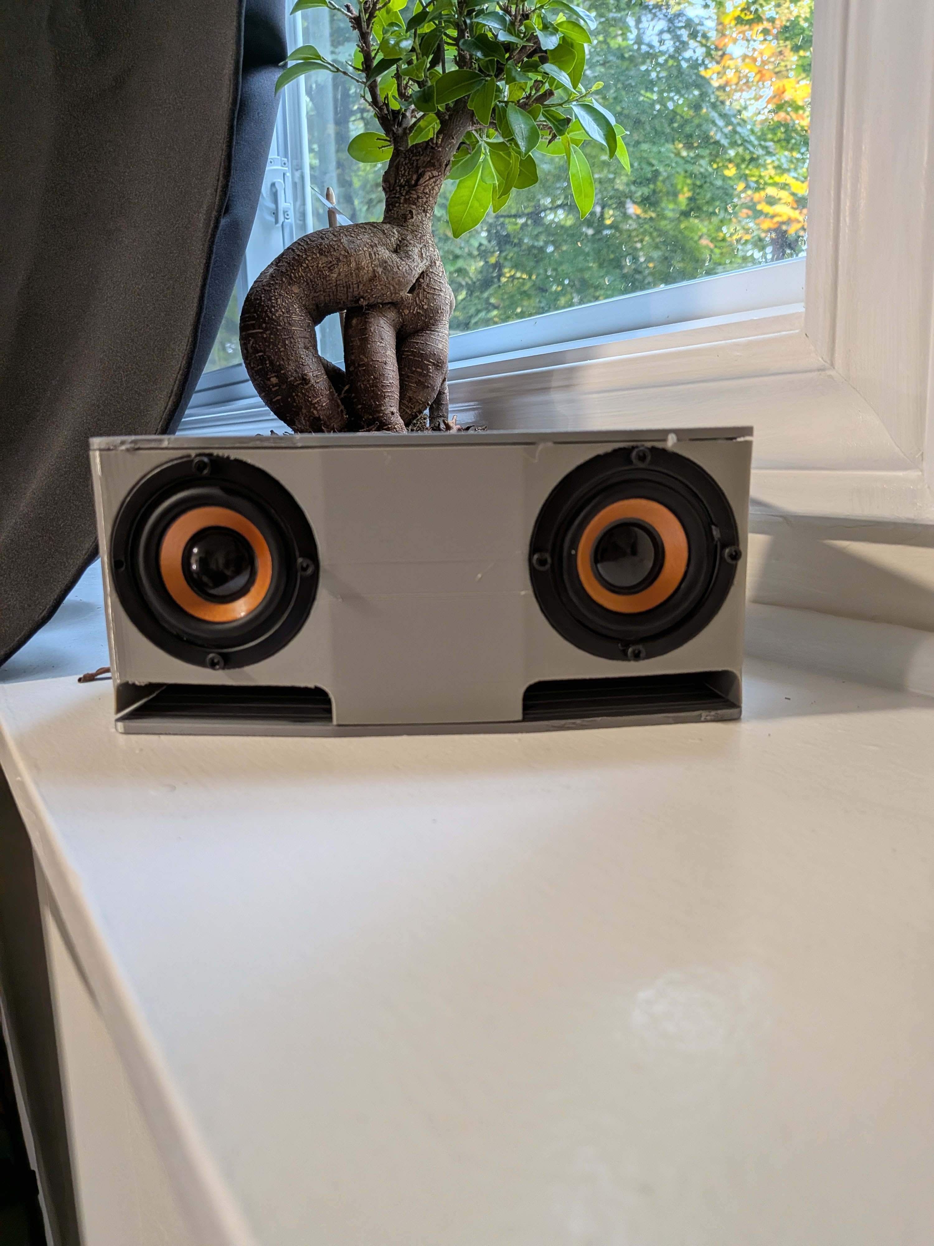
A custom speaker enclosure modeled in Autodesk Inventor with separate body and top/bottom pieces, exported as STL/3MF for 3D printing.

Autodesk Inventor3D Printing

Project Files

The enclosure was designed in Autodesk Inventor (.ipt files) with separate body and top/bottom components. 3D-printable exports (STL and 3MF) were generated for fabrication, and earlier design iterations are kept in the OldVersions folder.

Conveyor Belt 3D Printer cover image

Motion & Design Analysis · UNB Mechanical Engineering · Solo Project

Conveyor Belt 3D Printer

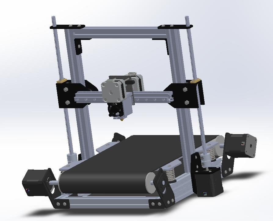
A low-cost conveyor belt 3D printer for continuous printing, inspired by the Creality CR-30 and buildable without a full machine shop. Aluminum extrusion and 3D-printed parts, a T8 lead screw Z-axis and a rack-and-pinion X-axis, verified with SolidWorks motion studies.

SolidWorksMotion StudyDesign for Manufacture

Abstract

The goal was a conveyor belt 3D printer that prints continuously while being built with simple tools and materials, keeping it low-cost and easy to manufacture. It was split into an upper frame and a base, modeled in SolidWorks using in-context design. The Z-axis uses a T8 threaded rod and the X-axis a rack and pinion, all driven by stepper motors.

A motion study showed a Z-axis ratio of 14.32 mm/s per rad/s and an X-axis ratio of 13.9 mm/s per deg/s. Most parts are printed or made with basic tools; only the rack gear and backplate need tight-tolerance machining.

Introduction

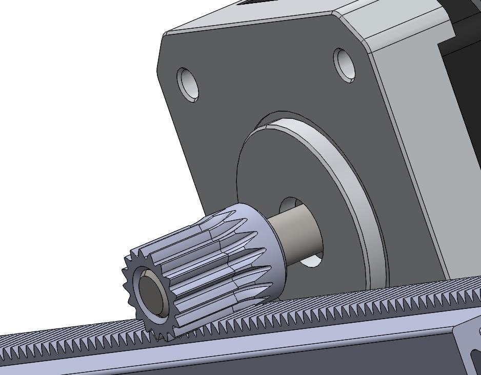
Inspired by the Creality CR-30 and an interest in automation, a conveyor printer allows continuous printing for mass-producing parts. Two mechanisms were studied: the threaded rod and nut that convert rotation into Z motion, and the rack and pinion that drives the extruder along X.

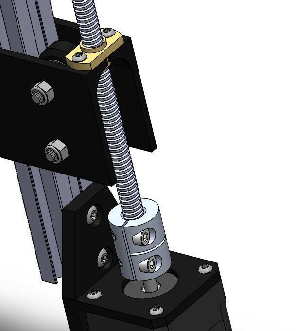
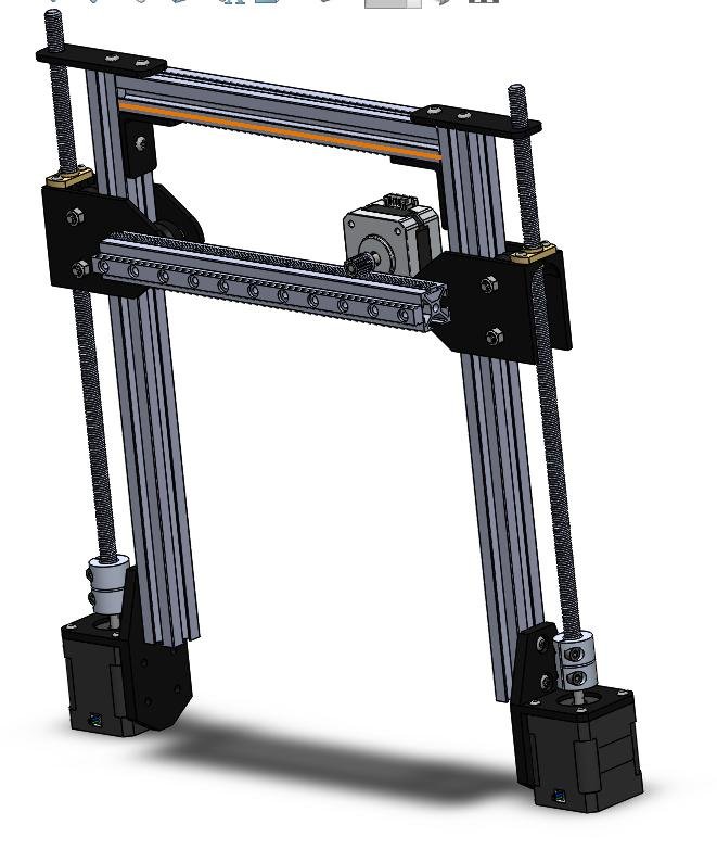
Figure 1: Mechanism
Figure 1: Mechanism
Figure 2: X-axis mechanism

Design Methodology

Rough sketches of the upper frame, base and extruder planned part counts and guidelines, speeding up design.

Base: aluminum extrusion for availability and workability. Drilling and tapping was replaced by 3D-printed joints, M4 screws and T-nuts. Adjustable stepper brackets drive the Y-axis belt and set belt height and tension, and the bearing brackets reuse the stepper screw pattern. A spring-adjustable build plate doubles as the belt tensioner.

Upper frame: the same extrusion and joints reduce unique parts. Z-axis steppers sit in custom brackets that also join the upper and lower assemblies; couplers drive T8 rods into brass flanged nuts on the X-axis supports. A linear guide rail replaces roller bearings for a compact profile with no tension adjustment.

Extruder: a backplate mounts the X-axis stepper and extruder — the most complex part, with six components on a compact surface, made possible by in-context design.

Figure 9: Finalized base assembly
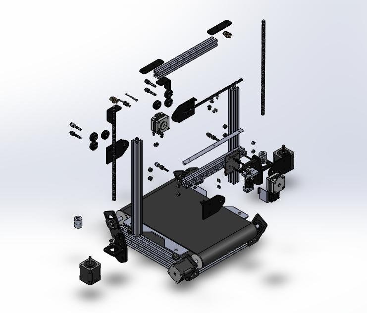
Figure 10: Upper frame exploded view

Lessons Learned

  • Mounting the X-axis stepper on the extruder adds weight and momentum (more print error, slower motion) and makes parts harder to make and repair.
  • In-context design was fast but caused cascading errors; references were deleted and parts fully defined afterward.
  • The motion study stalled with every part attached to the X stepper, so those parts were removed to analyze the rack and pinion.

Design Analysis

Velocity was used as the metric since displacement and acceleration gave noisy data. Z-axis: coupler rotation vs. vertical speed of the X-axis supports gave a ratio of 14.32, low because of the coarse T8 thread. X-axis: pinion rotation vs. linear motion gave 13.9 mm/s per deg/s.

Figure 11: Assembly used for motion study

Manufacturing

  • Rack gear — custom, best made by wire EDM (±0.0001 in).
  • Extruder backplate and heat sink mount — CNC milled to ±0.0025.
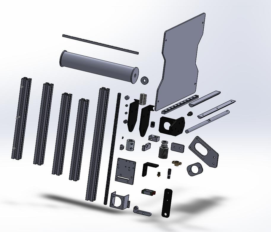
  • 3D printed — joints, washers, spacers, stepper mounts and X-axis supports, where tolerance matters less or is adjustable.
  • Aluminum extrusion — hand cut to ±0.1 mm with flat ends, drilled and tapped on a drill press.
Figure 12: Parts designed, spread out
Figure 38: Exploded view

Conclusion

The project involved problem-solving, planning, experimentation and frustration. Sketching first saved time, aluminum extrusion and 3D-printed joints minimized machining, and shared screw patterns cut the number of custom parts. Motion studies confirmed clear relationships between rotation and movement on both axes.

There is room to improve — especially relocating the X-axis stepper — but the design met its goals: simple, modular and buildable without a full machine shop. It’s a solid starting point for future iterations.

Resources

Build Guides

Coming Soon

Background

Resume

Download Resume PDF

Callum Ewen

Milton, Ontario

905-749-2209 · [email protected]

Education

University of New Brunswick, Fredericton

Mechanical Engineering Program · 2024 – 2028

SolidWorks CSWA Certification

Engineering Experience

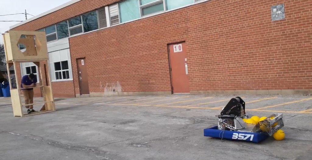
FIRST Robotics MDHS 3571 — Team Executive (2023), Lead Designer (2021–22)

In charge of a full student team by delegating project tasks while designing and custom machining (mills, lathes, CNC, laser cutters, 3D printing) robotic components including chassis, intake, and ball shooter.

Various Personal Engineering Projects

Designed and utilized FEA, CFD for multiple projects using findings to make changes for future design iterations. Multiple self-published projects with detailed fabrication guides and clear documentation for public use.

Work Experience

University of New Brunswick — Engineering Makerspace Facilitator

Feb 2026 – Present

  • Troubleshot, repaired, and maintained 3D printers and various facility equipment.
  • Adviser to engineering students on CAD and slicer setting optimization for 3D printing.
  • Supervised daily facility operations to enforce strict workplace safety protocols.

Dufferin Concrete (A CRH Company) — Operations Summer Student

Summers 2024 – 2026

  • Hands-on materials testing (slump, air, temperature, sample creation) and enforced strict quality standards, rejecting loads that did not meet standards.
  • Maintained plant machinery, managed landscape among various plants, admixture loading, and independently managed sample delivery across southwestern Ontario.

WSP — Field Services Assistant

Aug 2022 – Nov 2022

  • Responsible for independently completing inspections of city sidewalks to identify issues based on specific criteria.
  • Used GIS software on assigned tablet to identify issues and record locations as a digital footprint.

Additional Projects

Universal 3D Printed Cold Air Intake Design

Developed a reverse engineering workflow to design custom 3D printable cold air intakes by converting spatial mockups using formable pool noodles into CAD via 3D scanning. Optimized a personal iteration using Ansys Fluent CFD, while finding a universal material through hoop stress calculations and accounting for glass transition temperatures.

Lost Formed Carbon Fiber Manufacturing Process

Developing a lost core composite manufacturing process to create complex hollow parts by applying carbon fiber sleeving and resin over 3D printed PVB core, which is then dissolved via isopropyl alcohol. With full process documentation.

Supersonic Model Rocket

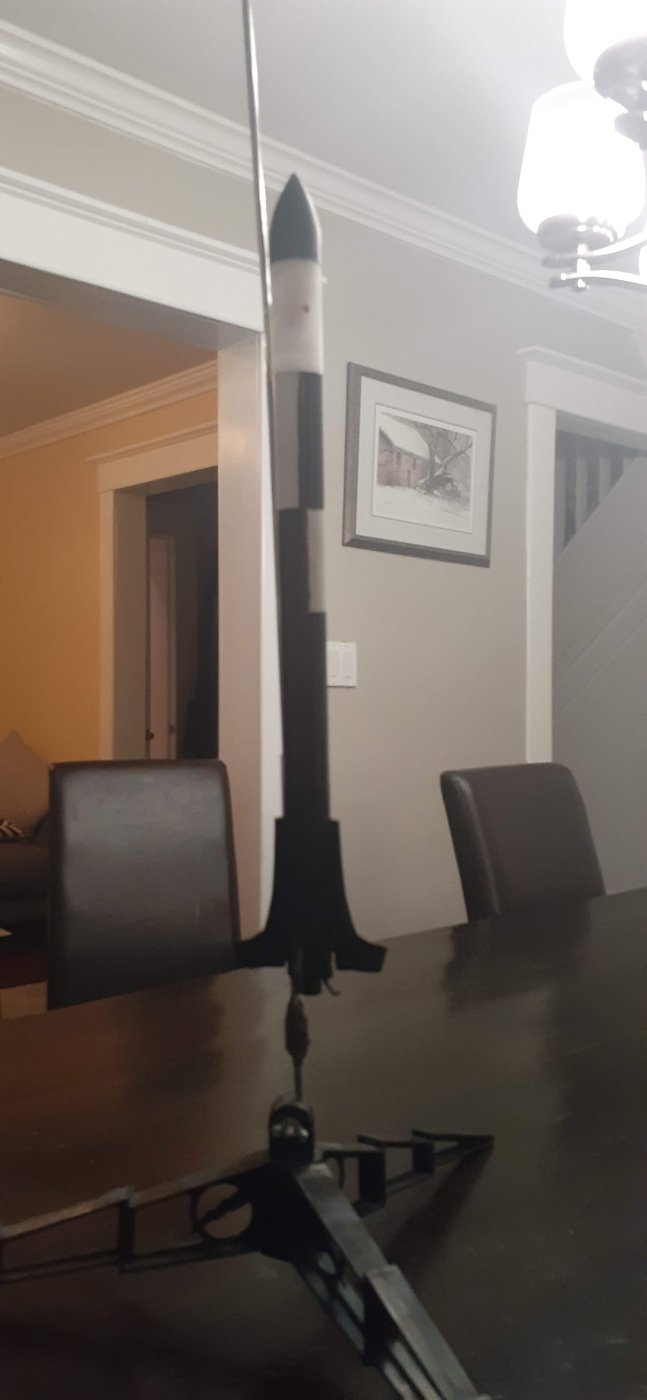
Engineered a Mach 1 rocket, performing extensive aerodynamic simulations in OpenRocket across multiple design iterations.

Skills & Certifications

SolidWorksAutodesk InventorFusion 360AutoCADMATLABArduinoPython (VS)3D Printing (Cura, Bambu, Prusa)CNCLaser Cutting (Trotec)LatheMillDrill PressBand SawSolderingWire RoutingCrimpingMicrosoft Office SuiteOntario H&S TrainingDriving Licence GDual Citizen (Canada & UK)

Hobbies

Skiing, Drumming, Hiking, Cooking, 3D Printing, CAD Design, Model Rocket Design, Hockey Goalie, Soccer, Rock Climbing, and Fitness.

About Me

Beyond the Workbench

Callum Ewen personal photo 1
Callum Ewen personal photo 2
Callum Ewen personal photo 3
Callum Ewen personal photo 4
Callum Ewen personal photo 5
Callum Ewen personal photo 6
Callum Ewen personal photo 7
Callum Ewen personal photo 8
Callum Ewen personal photo 9
Callum Ewen personal photo 10

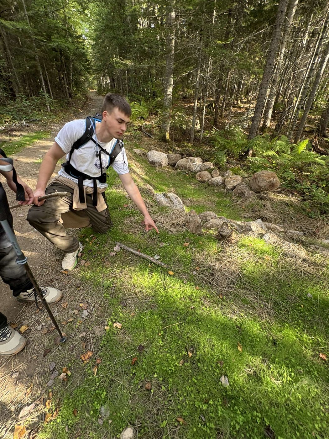
I grew up in Milton, Ontario, and lived there my whole life — until my brother, who played on the St. Thomas University soccer team, invited me out to New Brunswick. I fell in love with the province and decided to make the move.

I've taken on engineering projects throughout my life, and I have a true passion for making things and for the problem-solving process — finding unique solutions to challenging problems.

Outside of engineering, I love the outdoors and staying active. I regularly go hiking, train at the gym, and captain an intramural soccer team. At this point, I have too many hobbies to count.

Milton → NB
Hiking
Gym
Soccer Captain

Interests

SkiingDrummingHikingCooking3D PrintingCAD DesignModel Rocket DesignHockey GoalieSoccerRock ClimbingFitness

Get In Touch

Contact

Interested in collaborating or have questions about a project? Send a message below.